Quantcast
Channel: KF7LZE's Blog » philco
Viewing all 10 articles
Browse latest View live

Ruined Antique Radio Photo Roundup Redux

$
0
0

I thought I’d start the weekend off with some more photos of butchered antique radios for your viewing misery pleasure. This is the second-round photo roundup. Check out the first set of ruined antiques here!

An aspiring artist thought this 1940s Philco radio would look better painted in a motif reminiscent of Starry Night. I don’t really agree.

Somewhat similar, a dealer is selling a Zenith tombstone radio that’s been decoupaged with magazine clippings. This was almost an interesting work of art, but because the magazine clippings aren’t from the correct period, it’s just tacky.

This late ’20s lowboy radio was stripped down into an end table. Cleanly done but it would’ve been more interesting with the internals, even non-working.

From Craigslist, someone turned what I suspect is a late ’30s RCA into a bar with a modern stereo built in. Turning radios into bars seems to be a popular thing to do with them.

Radio bar conversions have been going on for a very long time – almost as long as radios have been around – and some can be very interesting. It’s just that many are done without respect for what the radio used to be – and without regard for the shape of the cabinet. Most upright radios don’t have a flat inside space to place anything, making shelving difficult – and ensuring that it’s going to look ugly no matter where it’s stored.

Most similar-looking Post-War consoles with a record player are reasonably suitable for conversions. This one has been adapted into a cigar bar:

That’s not too bad, but radios with more square space inside are even better:

I’ll be converting one in this style to a bar myself, soon:

Back in the 1930s, radiobars were intricate pieces of high-end furniture in custom made cabinets for the wealthy and were produced by several major brands. This 1937 Philco radiobar has great folding out sides and mirrored backing, with period glassware:

They came in a few cabinet styles:

There were even models produced into the ’40s and ’50s, like this Porto-Baradio mantle-top bar:

If you’re looking for an antique radio bar, you might be better off shelling out for an authentic one rather than a conversion.

And finally, leaving you with one that looks deceptively like a ruined antique but is in fact very special:

While it might look at first glance like a 1930s RCA radio that’s been painted black and had 1970s chair rails stuck on the ends, this is in fact an original by famed industrial designer and RCA contributor John Vassos and is worth thousands. Its style is the sort of thing that could be easily overlooked, too!


Antique Radio in “House” Season 8 Episode 5

$
0
0

In “House”, Season 8 Episode 5 (aired 11/7), we can see that the good Doctor has a 1937 Philco 37-620 Radiobar in his office. Unclear whether or not it has the original glassware. I’d love to have one of these in my collection, but they’re quite rare and expensive.

Philcoradio.com has some more about the history:

This Philco Radiobar sold for $252.50 in 1937 dollars, around $3800 in today’s money. This was a high end luxury for the wealthy to have in their homes, but out of reach of most consumers of the time.


More Strange Coiled Wires [Mailbag]

$
0
0

I had an interesting call the other day with a gentleman about a radio he’s working on, among other topics:

That’s a Philco 46-420. They’re nice little bakelite radios with 6 tubes designed to receive the AM broadcast band. He’d come across some unlabeled wiring while repairing and had dealt with it but we were talking about what it’s purpose was.

I generally work on pre-WW2 radios so haven’t run into this particular arrangement personally, but I’ve read a few different articles by other collectors on this topic and recognized it immediately. The coil, wound 8 turns around the capacitor and connected at one end to the chassis, is a type of wave trap designed to cancel out the inductance of the old capacitor. This helps to prevent interference – both received, picked up through the cap as if it were an antenna, and radiated interference from the signal passing through the cap. Philco used these capacitor wave traps in most of their radios from 1946 and on. There’s an article at the Philco Repair Bench describing one style; this is a slightly variation with the same effect.

Modern caps are constructed out of metalized polymer films that have very little inductance, but these older capacitors were just concentrically coiled metal foil sheets with a lot of natural inductance.

Bypass cap from my client's Grunow 589

Filter cap from my GE LF-116

1950s "Bumblebee" Cap Exploded - MyLesPaul Forums

0.1uF 400V TubeTime.us

Modern caps don’t have that physical property, so it’s safe to replace the wrapped capacitor with any modern replacement and either shove the new cap through the coil, or remove the coil entirely.

Thanks to Bob from Old Tyme Radio for these photos of his project, and for distracting me from being snowed in for a bit!

I’m always taking mail from readers with interesting anecdotes, photos and questions so feel free to send them over either as comments or through the e-mail address I’ve posted in my Repair Services page.


Welcome Back!

$
0
0

I’ve been offline for a bit as I’ve been too busy at my career to do much on the side. My workload has died down a bit and I’m back at it. Currently on my bench is a Philco 38-C-12 “Coronation” model.  It’s a Canadian model, with a 25-60Hz power transformer, but other than that it’s identical to the US model 38-12 code 121.

The tube line-up is 6A7 78 75 41 84. This was on the more economical side of price, and only one of the two IF transformers is located above the chassis and properly shielded. The other IF transformer is unshielded below the chassis and has some very specific lead dress instructions for professional service.

Again hinting at the economy nature of this radio, there are only a handful of capacitors that are immediately suspect. The unshielded IF transformer is visible at the bottom center of the radio, mounted perpendicular to the tube sockets.

The tuner on this model is nearly seized. It’s uncommon for them to be this badly stopped up, but not unheard of. I’ll be replacing this radio’s bad paper and electrolytic capacitors and cleaning and re-string the dial and tuner. Stay tuned, I’ll also have some more about exactly which coronation they’re talking about.


1938 Philco 38-C-12 “Coronation” Radio Repair

$
0
0

I’ve had this radio on my bench for a little while, and she’s finally back up and running – and it plays great! It’s a 1938 Philco 38-C-12, special edition to commemorate the crowning of King George IV and Queen Elizabeth.

Since we don’t have a King and Queen of the United States, it’s fairly obvious this radio isn’t from around here. This particular model was made in Canada and brought to the U.S. sometime later, and was actually rediscovered in Florida. I can only assume a retiree seeking warmer weather brought it with them sometime in the last 75 years, and that’s how it traveled the long distance itself.

Period Canadian radios came with a Ontario Hydroelectric Power Commission approval stamp, which makes it easy to tell their origin.

The power transformer also gives it away – the 25Hz transformers used in some parts of Canada at the time are considerably larger than the 60Hz transformers found on most American radios. (You can use a transformer rated for a lower frequency, as the greater amount of metal makes it less likely to saturate, but you generally can’t use a transformer rated for a higher frequency on a lower one.)

This radio has seen a little bit of service in the past – both can capacitors have been removed; one was cut open and used to hold its replacement in a partial restuff and the other was replaced below the chassis. All in all, though, the radio came to me in very good near-original condition. This radio uses five tubes 6A7 78 75 41 84 – which is a little different from the typical tube line-up, but allows a smaller power transformer to be used as the rectifier can take advantage of the same 6.3V windings for the rest of the tubes, rather than needing a dedicated 5V winding. Its schematic is the same as the American Philco 38-12.

Capacitor replacement was uneventful on this radio, but I also had to replace the tuning capacitor mounting gaskets. These isolate the frame of the tuning gang from the chassis to keep it from shorting out. Over time they shrink and harden. Renovated Radios has many types of reproduction chassis gaskets. The new ones have restored the right tuner height and isolation. This part was pretty labor intensive, but needed to be done for best performance.

You can see in the next shot, the braided ground strap from the tuning gang ready to be tacked back to the RF ground. Desoldering braid works perfectly for this application.

On top of all these problems, the dial pointer shaft was seized up. I removed the shaft, cleaned with 99% isopropyl rubbing alcohol, re-applied lubrication, re-mounted the shaft and restrung the dial cord. This one is very easy – spring mounts on the gang itself, and 1 1/2 turns around the tuning shaft for tension.

As you can see in this shot…the reproduction gaskets don’t fit 100% the same way the originals did. They work, though, and this part of the radio isn’t visible while it’s in the case. So it’s time to put it all back together and get the shields on:

Back in the case:

Fully serviced, this radio will continue playing for many years!

Feel free to leave comments and questions.


Don’t Trust Everything You Read (On Old Radio Schematics)

$
0
0

Electrical drafting is primarily done on a computer today, with software such as EAGLE or KiCAD. This wasn’t the case back when tube radios ruled the airwaves, though – schematics were drawn up by engineering draftsmen by hand. And as with any process with a human element, they didn’t always get it right.

I’m working on a 1934 Philco 66. It came to me in excellent original condition with little evidence of having been service, and throughout the process, I’d been relying on the schematics to guide me in the right direction. Unfortunately, along with a laundry list of other issues, my reliance on the schematic to be “the truth” led me around in circles longer than I needed to be to resolve a power supply problem.

Below is a schematic snippet of the power supply and audio sections of the 1934 Philco 66, with the RF chain to the left of the #75 Detector/1st Amplifier tube hidden for simplicity’s sake.

In green, I’ve highlighted the path B+ (high voltage) is supposed to flow from the rectifier cathode to the plate of the first audio amplifier. It’s a very straightforward path…if the draftsman had indicated that tube was supposed to be connected to the power supply. In red, I’ve indicated a missing connection symbol. Without it, there was no power being supplied to the first tube in the audio amplifier stage and the audio signal was being killed at that point before it could make it to the final output amplifier. Using an alligator clip, I restored that connection to test, and the radio sprang to life making noise on the next power-up.

The second filter capacitor should have been connected to both B+ and to the plate path for the #75 tube, rather than just the plate path. (Incidentally, the two capacitors are both at the same potential, so under the correct connection scheme could have been replaced with a single capacitor of a larger value.)

It’s not done yet, but I’m inclined to believe the final wiring issue has been corrected, and it’s on to performance.


A Most Convoluted 1934 Philco 66B Antique Radio Repair

$
0
0

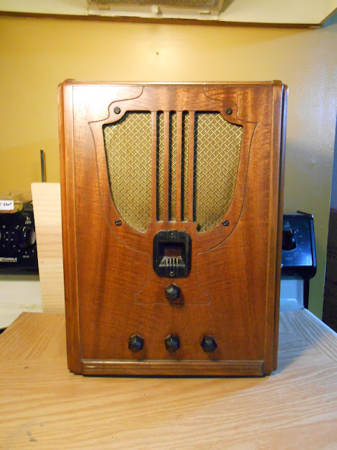
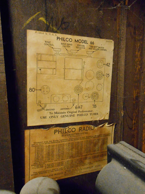
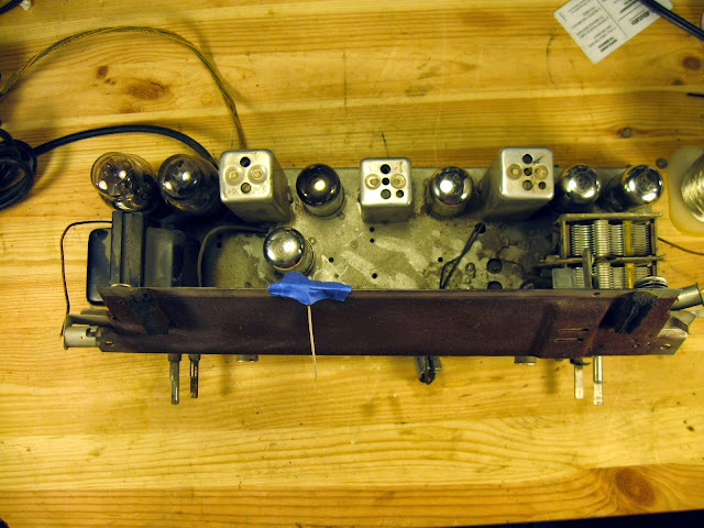
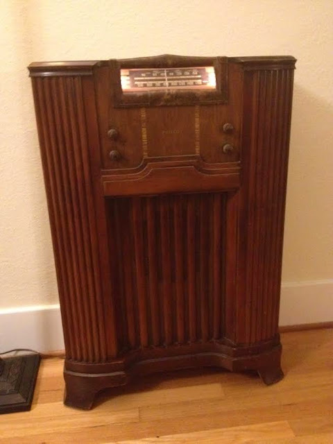
Recently, I took in a beautiful Philco 66B for repair. Manufactured in 1934, this chassis ended up in several different models – a couple of tombstones, a cathedral, and at least two console radios. They’re all 5-tube radios with the AM Broadcast Band and 1 Shortwave band.

Philco’s designs spanned the entire range of quality, with entry level sets being subject to various interesting design quirks of junior engineers and more advanced sets designed with tight tolerances. They did tend to use potted components longer than most other manufacturers that I’ve worked on, though, and that coupled with quite a few other issues made this one of the most challenging repairs I’ve completed with a lot of unexpected detective work.

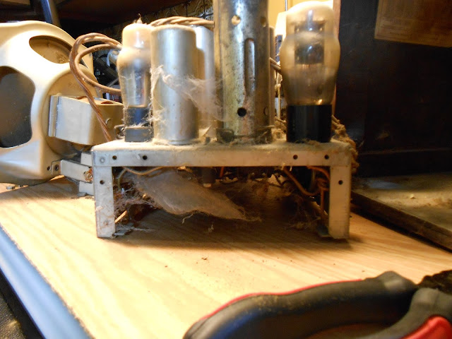
The tube line-up of 6A7 78 75 42 80 is very common. The 78 tube is effectively identical to the 6D6 tube, although they were developed separately. After testing, this radio needed a new 6A7, 78 and 75 tube which I replaced from my stock. A few spiders once lived inside but were clearly long since gone and were vacuumed out easily.

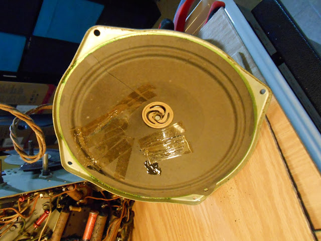
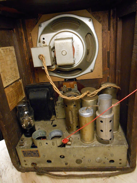
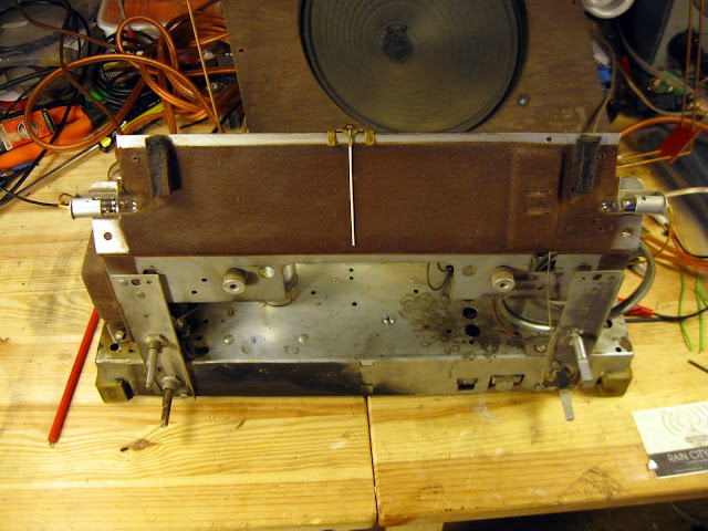
Something happened to the speaker at least twice in the past. There’s glue, and two different types of tape applied to the cone.

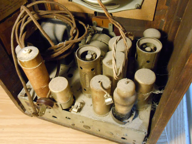
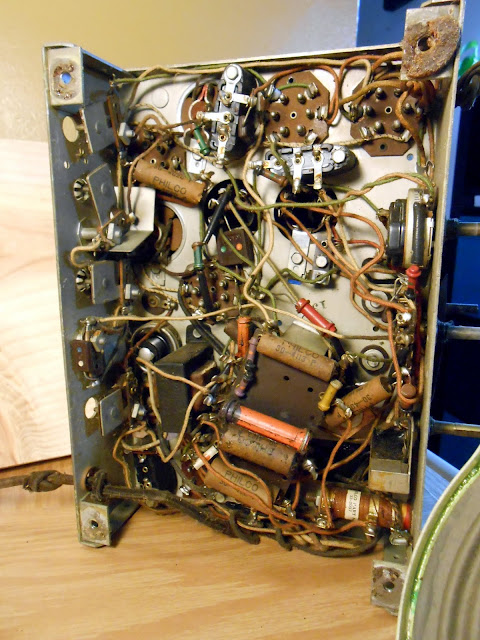
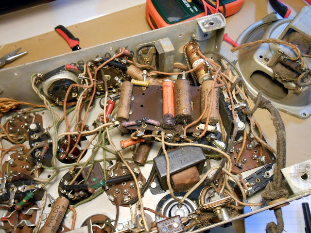
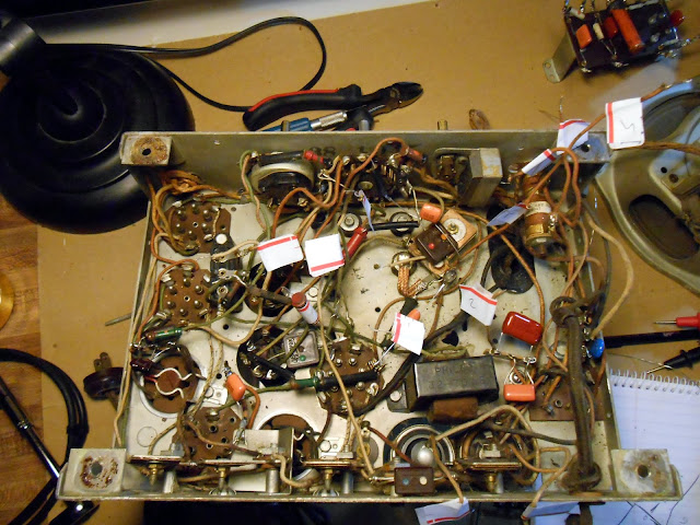
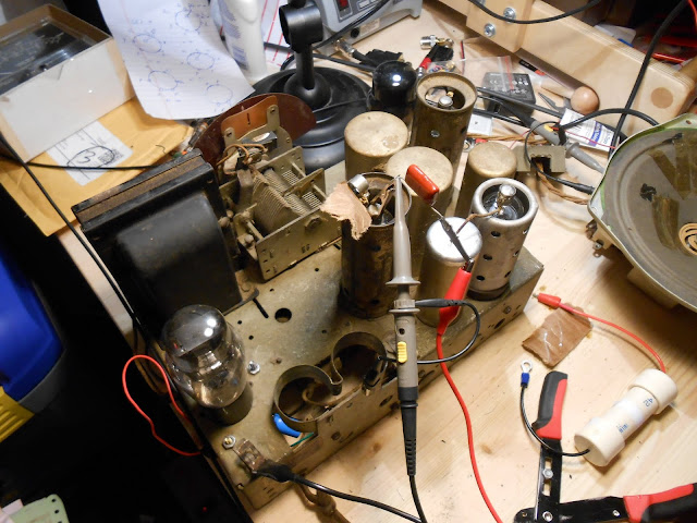
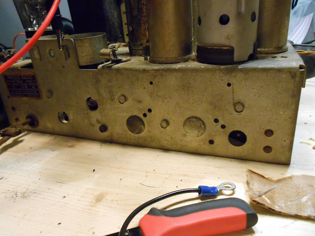
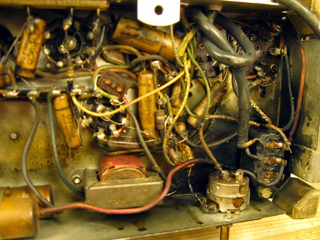
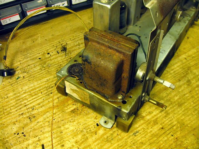
The underside looked untouched, or was serviced only at an authorized Philco retailer which replaced with branded components. I couldn’t say for sure.

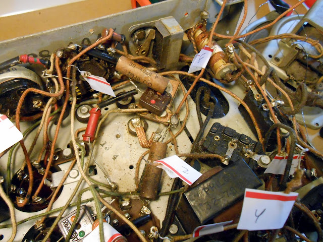
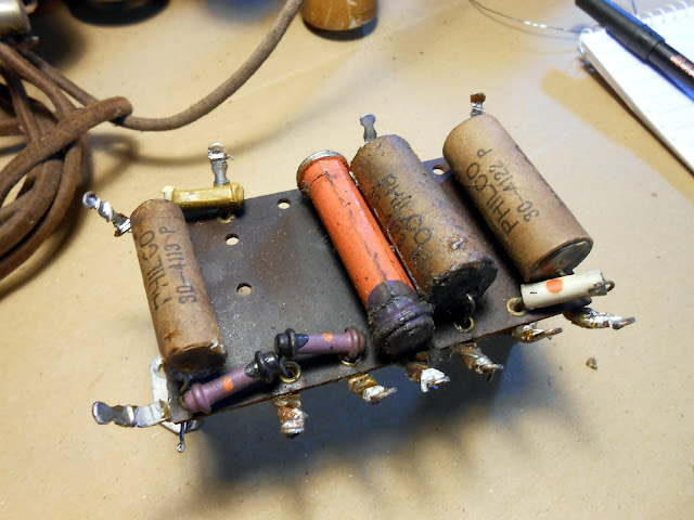
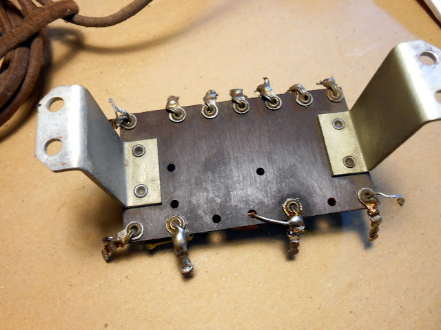
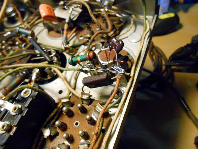
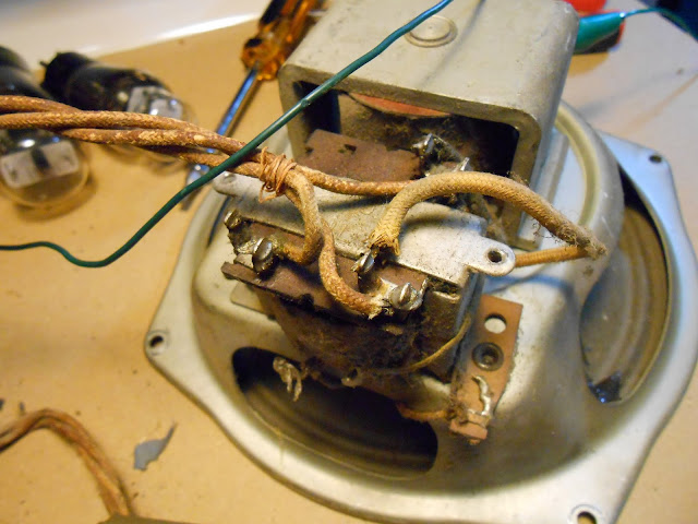
This model did have a terminal strip, stacking components in two layers. I had to disconnect a lot of wires to remove it to get at the connections below.

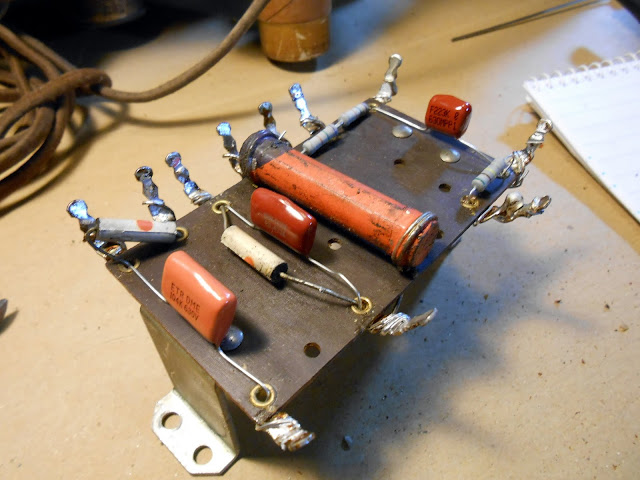
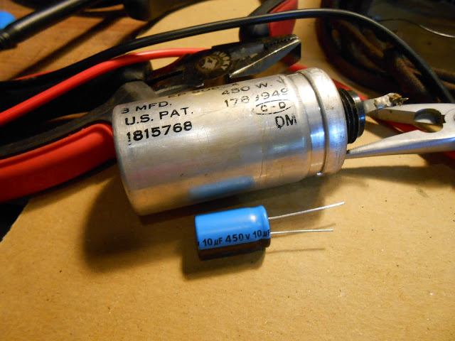
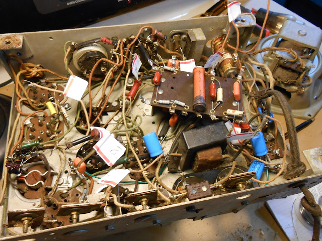
I replaced out of tolerance resistors and capacitors as normal, including the molded bakelite capacitors which I replaced with terminal strips and discrete capacitors. It would have been much easier to work on if Philco had switched to cardboard capacitors for all parts instead of only some.

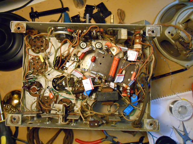
Time for reassembly.

The first power-up was a success! In the sense that nothing caught on fire, but it wasn’t making any noise – even when probing various circuit points listening for activity from the speaker. I spent quite a few hours troubleshooting and it turned out to be quite a few very subtle problems which only turned up after a lot of diagnostics. Each resolved problem revealed something new.

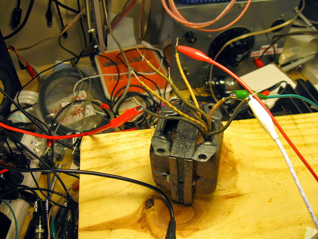
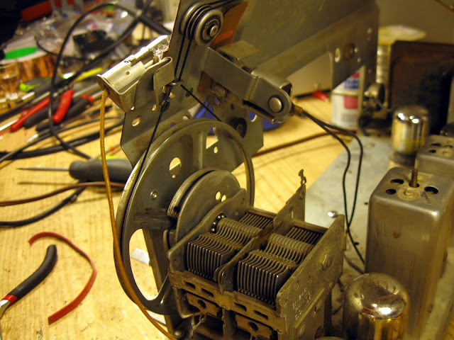
All the coils checked out, and initial checks revealed voltage all the places I expected it.

As it happened, I accidentally flicked off the power strip with the workbench light instead of the strip with the radio on it, and glanced down in the dark at the tubes to see a bright blue glow in the #42 output tube. That was the first failure. It wasn’t readily visible in the black getter tube under bright lighting, and the tube tested good on the first pass. It must have finally given up during the time it was powered on for troubleshooting. I replaced it with one from stock, and was able to get a few clicks and some minor static, but nothing significant. On a hunch I tested the resistance from various points in circuit to ground, and quite a few had drifted – but the resistors had been replaced! In other cases, the end of a capacitor to ground was several hundred ohms. The 1934 solder joints seemed to have failed. After I tightened down my new grounds and re-soldered others, the resistance was fixed, but it still wasn’t making noise.

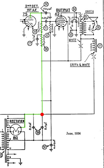
I removed a test jumper but noticed I wasn’t getting the right voltages, and it turned out now the #75 detector didn’t have plate voltage. Due to an error on the schematic from the draftsman in 1934, the capacitor’s connection to B+ was omitted.

In green, I’ve highlighted the path B+ (high voltage) is supposed to flow from the rectifier cathode to the plate of the first audio amplifier. It’s a very straightforward path…if the draftsman had indicated that tube was supposed to be connected to the power supply. In red, I’ve indicated a missing connection symbol. Without it, there was no power being supplied to the first tube in the audio amplifier stage and the audio signal was being killed at that point before it could make it to the final output amplifier. Using an alligator clip, I restored that connection to test, and the radio sprang to life making noise on the next power-up.

The second filter capacitor should have been connected to both B+ and to the plate path for the #75 tube, rather than just the plate path. (Incidentally, the two capacitors are both at the same potential, so under the correct connection scheme could have been replaced with a single capacitor of a larger value.)

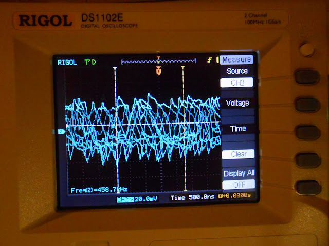
With the jumper back in place, the radio powered up and immediately tuned static across the range and it was on to final tweaks. This radio is very susceptible to interference even with the shield in place, but it picked up stations immediately with a 3′ antenna although some were weaker than others.  I hooked up my signal generator and oscilloscope.

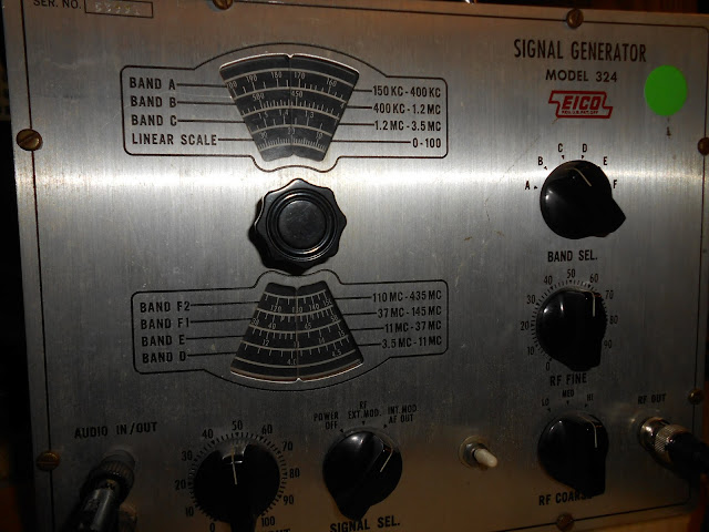
The Philco 66 uses a 460 kHz IF, so a nominal frequency of 458.7 kHz is close enough. The signal generator is from the 1950s, and even though it’s been reconditioned, it’s just not very stable – the frequency randomly fluctuated on either side of the center. I’d like to get a synthesized signal generator at some point. This was the same equipment that would’ve been in use at the time (or better), so it’s perfectly suitable for alignment.

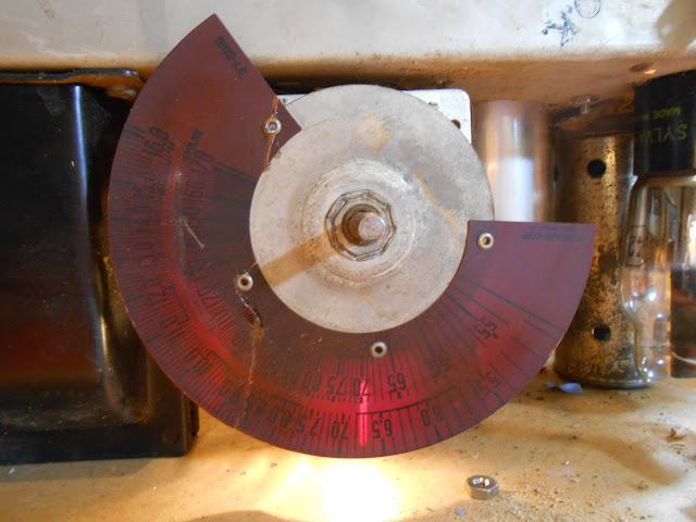
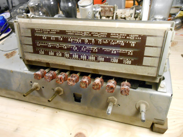
Somehow this Philco managed to keep its metal plugs to prevent accidental adjustment to the IF trimmers. I went through the alignment and peaked the dial at the appropriate locations. Then, everything went back together:

This model of Philco went through quite a few design revisions over its lifetime, which complicated the repair efforts – each variation had slightly different arrangements to defeat interference this model was very vulnerable to. Even perfectly repaired, this radio showed sensitivity even to switching on and off a work lamp near-by and feedback from ambient electronic noise. That’s just the reality of modern electronics life – there wasn’t the same kind of EM spectrum pollution back then there is now, and antique radios often just don’t have the ability to reject interference the way modern electronics do.

Even with the possibility of interference, this Philco came back to life beautifully and tuned across the entire range of AM broadcast stations, perfect for listening to Oldies or the Mariners’ game.

If you’re in the Seattle metro area, I can help bring your antique radio back to life – contact me!


1940 Philco 40-185XF Antique Radio Restoration

$
0
0

I had the privilege of working on a very well preserved Philco 40-185XF recently. These are top performing pre-war sets featuring 8 tubes, an RF amplifier front-end and push-pull audio output into a 12″ speaker. Definitely worth fixing up! This radio had been its owner’s family for years – first in his grandparent’s home, then with his parents, before it passed on to him. After serving as a conversation piece for many years, it was time to get it going again.

This model had been sitting silently since the 1970s and was ready to come back to life. It came to me for a complete overhaul, including testing all the tubes to replace as needed, re-stringing the dial, replacing hardened rubber mounts and eroded pushbuttons, and a precision alignment.

The underside is nicely laid out and pretty easy to work on. There’s a few capacitors which are buried, but most are easily accessible. The output transformer, top left, is mounted under the chassis instead of on the speaker as was more common on earlier sets.

Component replacement was initially pretty straightforward. The preset assembly was held in by two screws and had plenty of slack to fold it up and out of the way to allow easy access to the components beneath it. There were several small capacitors and an electrolytic can mounted under the pushbutton assembly.

The power cord was in dire need of replacement, so it received a new polarized plug and new X1Y2-rated safety capacitors on a newly mounted terminal strip.

With component replacement complete, it was time for a first power-up and a test signal. All seemed to be good at first for a bit…but then the radio sputtered a bit and cut out entirely – then some faint smoke started to appear! Bad, bad sign. I killed the power quickly to avoid damaging anything and carefully inspected the fault.

On this schematic snip, the resistor circled in red was the one which was overheating and smoking. This resistor feeds the high voltage to the front-end of the radio; overheating means excess current drawn. I pulled those tubes, but it continued to smoke, so further investigation was necessary. First, I replaced that resistor with a new one which hadn’t been heat-damaged.

It’s a bit faint, but the insulation had cracked off the wires leading into the IF can and were shorting to the chassis. That’d be the problem! Time to pull the IF can:

Some wires were cloth and some rubber-coated; some of the rubber coated ones were fine, and some were brittle and cracking. I sleeved the damaged wires, then reinstalled the transformer in the can and mounted it back up. One problem solved! The short circuit was fixed, but there was still no audio output – even when injecting directly into the audio amplifier circuit.

There were some clicks when I’d touch certain resistors with a probe. The resistors had overwhelmingly tested within tolerance so most were left original, but something happened along the way. I pulled the suspect resistors to replace, and examined the old one:

It’s tough to see – but the body of the resistor is cracked! This was a new problem. What happened is: carbon composition resistors absorb moisture from the atmosphere over time. In this case, the radio is 74 years old, and 44 of those years it sat without being played. Resistors also dissipate heat when they’re operating. This combination caused the absorbed moisture to expand and escape by cracking the body of the resistor and causing intermittent opens. Not good for performance! I replaced nearly all the remaining resistors at this point.

The replacements are 1% tolerance precision metal film resistors which should last for a very long time, and don’t absorb moisture the way carbon resistors do. Now, I was able to get audio, but no radio reception. Testing the front-end verified the radio was operating, but it wasn’t tuning a signal. Time to investigate the band switch – which, surprise, was badly gunked up! The mechanism wasn’t allowing the tuning capacitor to engage, and all the contacts were badly corroded which was killing the signal.

You can see how much gunk and oxidation had caked up onto the switch contacts – on the left, not processed; on the right, cleaned and scrubbed.

With that, the radio roared to life and picked up stations loud and clear across the dial! There were a lot of problems, but they were all able to be corrected. I peaked up the alignment using my standard signal generator, then did final inspection checks.

Finally, it was ready for the trip home! It sounded even better installed back in the cabinet.

The owners had the cabinet refinished while the radio was in the shop – it’s a perfect pairing! New pushbuttons and new rubber mounts and the radio is nearly as nice as they day it left the showroom floor.

This family heirloom is back in running shape and is going to serve faithfully for many years to come as a beautiful piece of functional furniture. Just look at it!

If you need your antique or vintage radio repaired in the Seattle area, contact Rain City Audio.


Philco 42-365 Antique Radio Repair

$
0
0

Cross-posted from the Rain City Audio Repair Blog:

This Philco 42-365 came to the shop in need of major repairs. It was missing its dial string, lamps, and the power transformer had melted down due to a failure in the main electrolytic capacitors.

It’s melted and run everywhere, and left quite a bit of smoke residue. Fortunately, the power transformer on this model was also used on a few models spanning several years, so it was fairly readily available.

Transformer leads back then weren’t always labeled with standard conventions, so it’s always important to test them.

The replacement has a bit of surface rust but otherwise works perfectly.

The dial cord on this model is two separate strings wrapped around 5 pulleys, but it went back together okay.

It all went back together! The dial scale on this model is attached to the cabinet, and the owner brought the chassis and speaker alone, so I aligned the IFs but wasn’t able to align the dial tracking.

Back in its cabinet, though, it looks great!

Rain City Audio can fix your vintage radio, too.


Philco 39-45 Retrofit to 40-201 Cabinet Vintage Radio Repair

$
0
0

Cross-posted from the Rain City Audio Repair Blog:

A local customer approached me with his family’s Philco 40-201 vintage radio to be restored back to working condition. It had sat for several decades, very well preserved, but ultimately needed some service after the years.

Very unfortunately, however, the original chassis had a bad case of the notorious Philco coil rot and while its audio section was fully intact and the power supply in good condition, the RF coils were rotted and couldn’t be repaired. Thus it was time to find another chassis to put into the opening.

The oscillator coil, along with most of the RF coils, were the defective components on this one. This was a particularly insidious failure: the coils tested okay with a multimeter, but failed to oscillate due to green coil rot inside the windings, shorting turns together and killing the resonance. It took quite a few hours of diagnostics to narrow this down, since it was so subtle.

There are several chassis that will fit the opening, but the one I happened to find was from a Philco 39-45. They’re identically shaped, have the same dial scale, but some circuit differences. While the 40-201 uses primarily loctal tubes with the exception of the rectifier and #42 power output tubes, the 39-45 uses a mixture of octal and pre-octal tubes. The 39-45 uses a three-gang tuner and a tuned RF amplifier stage, which actually makes it a bit better of a performer than the 40-201.

The replacement chassis came partially recapped and verified working; I replaced the remainder of the capacitors and did an alignment.

Finally, it was time for an alignment. It peaked up pretty close.

Finally, back in the case!

On the first trial run, it sounded fantastic – picking up AM stations across the dial, and very surprisingly about a half-dozen shortwave stations in Arabic, Spanish, English, and several other unidentifiable languages. It’s going to be a great performer – and a wonderful family heirloom – for a long time to come.

Rain City Audio Vintage Radio Repair


Viewing all 10 articles
Browse latest View live